光线追踪简述
光线追踪(Ray tracing)是三维计算机图形学中的特殊渲染算法,跟踪从眼睛发出的光线而不是光源发出的光线,通过这样一项技术生成编排好的场景的数学模型显现出来。这样得到的结果类似于光线投射与扫描线渲染方法的结果,但是这种方法有更好的光学效果,例如对于反射与折射有更准确的模拟效果,并且效率非常高,所以当追求高质量的效果时经常使用这种方法。
光线追踪分为两种:
- 对象顺序渲染(object-order rendering):依次渲染每一个对象,然后更新每一个新对象对其它对象的影响。
- 图片顺序渲染(imageorder rendering):依次渲染像素,渲染每一个像素是考虑到每一个对象对它的影响。
光线追踪器一般来说可以很好地解决对象顺序框架难以解决的阴影和反射问题。
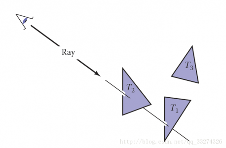
光线追踪的基本算法
光线跟踪器通过一次计算一个像素来工作,并且对于每个像素,基本任务是找到在该像素在图像中的位置处看到的对象。每一个像素表示摄像机“看向”的不同方向,可以看到的对象一定会和视线相交。因此,距离摄像机最近的对象时尤为重要的,因为它遮挡了后面的其它对象。
基础的光线追踪器包含以下三个部分:
- 光线产生(ray generation):基于摄像机的几何性质计算每一个像素的视线的原点和方向
- 光线相交(ray intersection):找到最近和视线相交的物体
- 着色(shading):基于光线相交的结果计算最近物体的颜色。
光线追踪一般程序如下所示:
for each pixel do
     compute viewing ray
     find first object hit by ray and its surface normal n
     set pixel color to value computed from hit point, light, and n
透视
最简单的是正交投影:
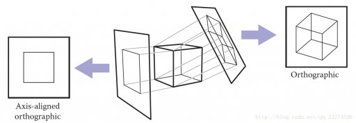
如果平面和视线方向是平行的,这种投影叫做正交投影,否则叫做斜投影;视线汇聚到一点,则是透视投影。

计算视线(view ray)
一条光线仅仅包含一个原点和传播方向的,因此非常适合使用三维参数方程进行模拟。
在参数方程中\mathbf p(t)=\mathbf e + t(\mathbf s − \mathbf e) ,\mathbf e 表示起点(eye),\mathbf s 是平面上一点,给予参数 t 可以计算直线上任意一点。
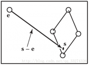
光线都来自于同一个摄像机框架,原点为\mathbf e,\mathbf u、\mathbf v、\mathbf w表示三个基本向量,\mathbf u指向光线的右侧,\mathbf v指向上方,\mathbf w指向光线相反方向,这是一个右手坐标系。
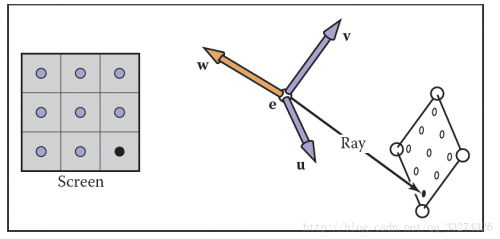
正交视图
在正交视图中,所有的光线的方向都是\mathbf -w ;透视投影的方向则是起始点到像素点。
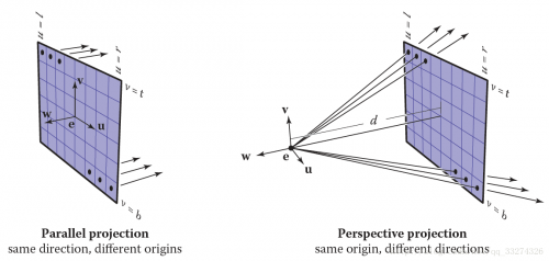
假设屏幕有n_x*n_y个像素,大小为(r−l)(t−b) 可以计算每一个像素的光栅化位置为:u=l+(r−l)(i+0.5)/n_x v=b+(t−b)(j+0.5)/n_y 产生正交视图光线可用如下方法:
compute u and v using
ray.direction =−\mathbf w
ray.origine =\mathbf e + u\mathbf u + v\mathbf v
透视视图
在透视视图中,所有的光线都有同一个原点。
透视视图的伪代码如下所示:(d 表示从视点到平面的距离)
compute u and v
ray.direction =−d\mathbf w + u\mathbf u + v\mathbf v
ray.origin = \mathbf e
光线和物体相交
产生光线 \mathbf e+t\mathbf d 后,就可以取 t 从 0 到无穷大来和物体相交。
光线与球面相交
已知光线 \mathbf p(t) = \mathbf e + t\mathbf d 和图形的表面方程 f(\mathbf p) = 0,当光线和表面相交时,那么顶点 p 一定满足表面方程,即:f (\mathbf p(t )) = 0 \quad or\quad f (\mathbf e + t\mathbf d) = 0 对于球面相交,设球心 \mathbf c = (x_c, y_c, z_c),半径为 R,那么球面的方程为:(x − x_c)^2 + (y − y_c)^2 + (z − z_c)^2 − R^2 = 0
向量形式为:(\mathbf p − \mathbf c) · (\mathbf p − \mathbf c) − R^2 = 0即 (\mathbf e + t\mathbf d − \mathbf c) · (\mathbf e + t\mathbf d − \mathbf c) − R^2 = 0 可以重写为:(\mathbf d · \mathbf d)t^2 + 2\mathbf d · (\mathbf e − \mathbf c)t + (\mathbf e − \mathbf c) · (\mathbf e − \mathbf c) − R^2 = 0 以上方程满足二次方程 At^2 + Bt + C = 0
先求解 B^2 − 4AC,若值大于零,则有交点,若值等于零,则光线与球面擦过,小于零则无交点。以下是 t 的值:t=\frac {-\mathbf d · (\mathbf e -\mathbf c)\pm \sqrt{\mathscr A}}{\mathbf d · \mathbf d} \mathscr A=\mathbf d · (\mathbf e-\mathbf c))^2-(\mathbf d · \mathbf d)((\mathbf e-\mathbf c) · (\mathbf e-\mathbf c)-R^2
光线与三角形相交
有许多算法可以计算光线和三角形的交点。我们将使用质心坐标来表示包含三角形在内的平面,因为这样就不需要长期保存除三角形顶点以外的数据。
已知光线方程,可以求得与三角形平面的交点时 t、u、v 值,f(u, v) 表示平面方程:

取得平面上不共线的三点,就可以表示整个平面,三角形满足,所以有\mathbf e + t\mathbf d = \mathbf a + β(\mathbf b − \mathbf a) + γ(\mathbf c − \mathbf a) 当β > 0 且 γ > 0 且 β +γ<1 时,交点在三角形内。否则光线与三角形不相交。
将上式分解,得


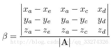
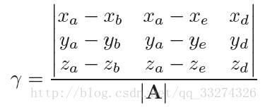


在求解如下 3 X 3 行列式时:
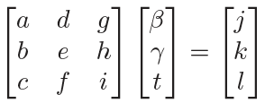
有许多元素可以重复使用:
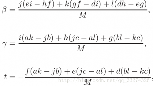
那么就可以得到以下算法:
boolean raytri (ray r, vector3 a, vector3 b, vector3 c, interval [t0, t1])
compute t
if (t < t0) or (t > t1) then
     return false
compute γ
if (γ < 0) or (γ > 1) then
     return false
compute β
if (β < 0) or (β > 1 − γ) then
     return false
return true
光线与多边形相交
给予 m 个顶点从 \mathbf {p_1} 到 \mathbf {p_m} 和法向量 \mathbf n ,对于直线 \mathbf p = \mathbf e + t\mathbf d,和平面上的点相交方程为(\mathbf p − \mathbf {p1}) · \mathbf n = 0 ,可以解得t={{(\mathbf p_1-\mathbf e) · \mathbf n}\over{\mathbf d · \mathbf n}} 然后就可以解得 \mathbf p,如果 \mathbf p 在多边形内,就相交。
最简单的方法就是从 \mathbf p 点发射任意射线,如果和多边形相交数为奇数,则表示在多边形内,否则在多边形外。
不妨设延 x 轴传播:\begin{bmatrix} x\\ y\end{bmatrix}=\begin{bmatrix} x_p\\ y_p\end{bmatrix}+s\begin{bmatrix} 1\\ 0\end{bmatrix} 在 3D 中如果多边形投影到 xy 平面是一条直线,我们则相应的转换到 yz,zx 平面即可。
if (abs(zn) > abs(xn)) and (abs(zn) > abs(yn)) then
     index0 = 0
     index1 = 1
else if (abs(yn) > abs (xn)) then
     index0 = 0
     index1 = 2
else
     index0 = 1
     index1 = 2
在实践中,一般将多边形转换为多个三角形。
光线和一组对象相交
通常场景会包含大量的对象,简单的方式是只计算最近的相交,即只关注最小的 t 值,这个 t 值在 [t_0, t_1] 之间:
hit = false
for each object o in the group do
if (o is hit at ray parameter t and t ∈ [t0, t1]) then
     hit = true
     hitobject = o
     t1 = t
return hit
着色
当找到了可视表面的像素点之后,就可以使用着色模型来计算像素值。
大多数的着色模型都是设计用来模拟光的反射,物体表面将会被光源和反射到摄像机的光照亮。
比较重要的向量有反射点到光线的方向 \mathbf l ,反射点到视点的方向 \mathbf v,表面法向量 \mathbf n,一般都使用法向量,还有一些表面的属性:颜色(color),高亮(shininess)等。
Lambertian 着色法
L = k_d I max(0, \mathbf n · \mathbf l) L 是像素颜色, k_d 是散射系数, I 是光照强度, \mathbf n 和 \mathbf l 是光源方向和法向量的单位向量。
Blinn-Phong 着色法
L = k_d I max(0, \mathbf n · \mathbf l) + k_s I max(0, \mathbf n · \mathbf h)^p \mathbf h 是半角向量,k_s 是高亮系数,p 为Phong指数
Ambient 着色法
L = k_a I_a + k_d I max(0,\mathbf n · \mathbf l) + k_s I max(0, \mathbf n · \mathbf h)^n k_a 是环境系数,I_a 是环境光照强度
多点光源
光有一个非常有用的性质——叠加性,可以得到多点光源下的计算公式:L = k_a I_a +\sum_{i=1}^n[k_d I_i max(0, \mathbf n · \mathbf l_i) + k_s I_i max(0, \mathbf n · \mathbf h_i)^p]
光线追踪编程
以下是对以上的一个总结:
for each pixel do
     compute viewing ray
if (ray hits an object with t ∈ [0,∞)) then
     Compute n
     Evaluate shading model and set pixel to that color
else
     set pixel color to background color
在实际实现中,一般需要返回被击中的对象。在面向对象实现中,实现 surface 类,然后衍生出子类 triangle、sphere、group,那么相交时就可以直接返回指向 surface 的指针。
光线追踪程序的面向对象设计
光线追踪器的重要类型结构是构成模型的对象。它们衍生自一些几何对象类,每一个对象都应该支持一个 hit 函数。任何可以被 hit 的对象都应该是这个类型结构的一部分,比如说包围盒,它们没有实际形体,但它们仍属于类中的一员。
比方说,基类需要声明 hit 函数已经包围盒函数:
class surface
     virtual bool hit(ray e + td, real t0, real t1, hit-record rec)
     virtual box bounding-box()
(t_0, t_1)是光线的有效距离,rec 是返回被击中物体的引用。
比方说,球的包围盒可以为:
box sphere::bounding-box()
     vector3 min = center − vector3(radius,radius,radius)
     vector3 max = center + vector3(radius,radius,radius)
     return box(min, max)
另外一个比较重要的类是材质(material),可以抽象材质行为,然后自由地往中间添加材质信息。
一个连接对象和材质的简单方法是在 surface 类中添加一个指向材质的指针。
阴影
如果点 \mathbf p 到光源的射线 \mathbf p + t\mathbf l 没有击中物体,则它不在阴影下,否则,在阴影下,下图所示为阴影光线(shadow ray)。
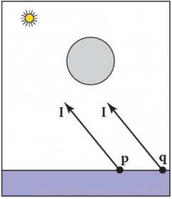
阴影光线的 t 范围本应该从 t ∈ [0,∞),但是由于数字精度的问题,我们给它一个小的偏移值 ε

function raycolor( ray e + td, real t0, real t1 )
hit-record rec, srec
if (scene→hit(e + td, t0, t1, rec)) then
     p = e + (rec.t) d
     color c = rec.ka*Ia // ambient
     if (not scene→hit(p + sl, ,∞, srec)) then
          vector3 h = normalized(normalized(l) + normalized(−d))
          c = c + rec.kd I max (0, rec.n · l) + (rec.ks) I (rec.n · h)rec.p
     return c
else
     return background-color
在光线碰到物体后多增加了一个判断,从视线发出一道光,几种物体后记录 \mathbf p 值,再从 \mathbf p 值往光源方向发出一条直线,如果没有物体相交,则计算 diffuse 和 specular 值,否则返回 ambient。
理想的高亮反射
使用镜面反射是非常直白的,反射光线可以通过法向量和入射光线来求:\mathbf r = \mathbf d − 2(\mathbf d · \mathbf n)\mathbf n 在现实生活中,反射时会损失一些能量,而且损失能量的多少与颜色有关。
可以增加一个 raycolor 的递归调用:
color c = c + km*raycolor(p + sr, ε, ∞),
k_m 是高亮的 RGB 颜色,为了防止无限递归,我们一定设定一个深度。
参考:Fundamentals of Computer Graphics, Fourth Edition